
Electrolock is a boltless restrained joint system with a double chamber socket to be used in Ductile Iron (DI) pipelines. It uses the same gasket as the normal push-on joint. The second chamber accommodates mechanical anchorage provided by specially designed locking bars or plates. It locks with a weld bead made on the jointing spigot. Electrolock joint Ductile Iron (DI) pipes are supplied with compatible Electrolock type Ductile Iron (DI) Fittings. Restrained joints are designed and tested as per the provisions of ISO 2531, EN 545 and ISO 10804.
Before the advent of Ductile Iron( DI) Pipes and Fittings (DI) pipes with boltless restrained joint, the older restrained joint design required cumbersome bolting arrangements with a separately cast follower gland, to serve the purpose of physically restraining the joint. However, in the new ‘Electrolock’ design no bolting is required to do the restraining. The advantages are manifold:
The thrust force developed in a Ductile Iron (DI) pipeline is dispersed along the calculated restraining length with the help of:
The concept is explained with a sample force diagram showing the thrust force and resistance forces at horizontal bend -
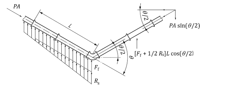
Where,
P: Thrust force developed by internal pressure
A: cross sectional area of pipe
Rs: Unit bearing resistance / Passive soil resistance
Ff: Unit frictional resistance / skin friction
L: Restrained length
The Electrolock restrained joint comprises of two chambers. It uses the same gasket as the normal Ductile Iron (DI) pipe push-on joint in the inner chamber to provide leak tightness. The second chamber accommodates mechanical anchorage provided by specially designed locking bars or plates. It locks with a weld bead made on the jointing spigot of the Ductile Iron (DI) pipe.
Some of the areas of application of Electrolock joint in a Ductile Iron(DI) Pipeline are –
Since there is no cumbersome bolting is involved in this type of restrained joint, Ductile Iron (DI) pipe and Fittings with Electrolock joints can be disassembled by removal of rubber blocks followed by unlocking the locking bars/plates and by removing them through the front slot one by one.
The unique quality of Ductile iron (DI) pipe restrained joint system is, it retains the joint flexibility, while providing physical restraint against axil pull and prevents longitudinal joint separation. Joint flexibility means that the jointing pipe can be deflected from a straight line by certain angle of deflection, as declared by the manufacturer. The allowable angular deflection for Electrolock joint is given below:
| DN | Maximum angular joint deflection (in degree) |
|---|---|
| 80-125 | 5 |
| 150 | 5 |
| 200 | 4 |
| 250 | 4 |
| 300 | 4 |
| 350 | 3 |
| 400-500 | 3 |
| 600 | 3 |
| 700-1000 | 3 |
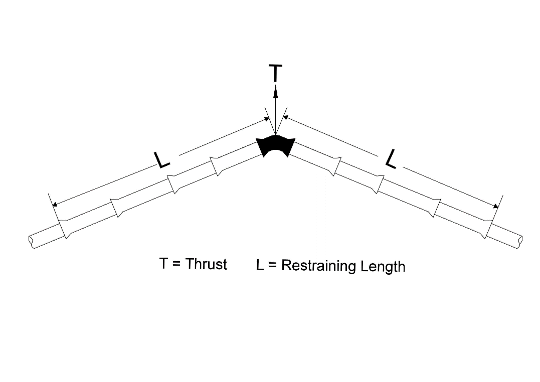
In a typical Ductile Iron (DI) pipeline with restrained joints, the thrust force is calculated and then a system of restrained jointed components, comprising a restrained jointed Ductile Iron (DI) fitting and a requisite number of restrained joint pipes on the upstream and downstream side of the DI fitting are installed to combat the thrust force. The length of pipeline to be restrained is calculated based on the pipeline pressure, type of fittings, surrounding soil parameters and backfill compaction level, as per the provision of ISO:21052.
An Electrolock joint is a double chambered restrained joint, where the inner chamber of the joint houses the normal push-on joint gaskets of EPDM (Ethylene Propylene Diene Monomer) and it does the joint sealing
The length of Ductile Iron (DI) pipes to be restrained is calculated as per ISO 21052:2021-“Restrained joint systems for ductile iron pipelines — Calculation rules for lengths to be restrainedâ€, where the calculation methodology is explained in details.
As per clause No. 11 of ISO 21052,… “Only in extraordinary circumstances, e.g. unstable soils, high internal pressure in combination with very shallow cover and exposed pipeline, the joint security is threatened. In these situations, the entire pipeline should be restrained and additional arrangements should be provided so that the angular deflection remains within the prescribed limits.â€
The pressure bearing ability of a Ductile Iron (DI) restrained joint is declared by the manufacturer based on the type test of the joint conducted by the manufacturer. The table below gives value for allowable operating capacity of Electrolock joint.
| DN | Pressure (in Kg/cm2) |
|---|---|
| Allowable operating pressure(without surge) | |
| 80-125 | 64 |
| 150 | 55 |
| 200 | 44 |
| 250 | 39 |
| 300 | 37 |
| 350 | 32 |
| 400-500 | 30 |
| 600 | 27 |
| 700-1000 | 25 |
Boltless restrained joint is preferred for trenchless laying mainly due to following factors –
A properly designed, restrained pipeline uses the passive bearing strength of the soil and frictional resistance of the soil. Calculation of restraining length depends on certain parameters which are:
Detailed calculation can be done as per the method explained in ISO 21052:2021-“Restrained joint systems for ductile iron pipelines — Calculation rules for lengths to be restrainedâ€.
A sample cost comparison between supply and installation of Electrolock restrained joint pipes & fittings and supply and installation of socket and spigot joint pipes and fittings with construction of thrust blocks in 1.2 MPa design pressure (WT is at ground level) in cohesive–granular soil (depth of cover is 1m):
| Nominal Diameter of Pipeline (DN) = | 400 (K9) | Bend angle = | 45° Horizontal Bend | ||||
|---|---|---|---|---|---|---|---|
| SL No. | Description of Work | Unit | Quantity | Unit Cost DI Socket & Spigot Joint Pipes & Fittings (Rs.) | Total Cost of DI Socket & Spigot Joint Pipes and Fittings (Rs.) | Unit Cost of Electrolock joint Pipes & Fittings (Rs.) | Total Cost of Electrolock joint Pipes & Fittings (Rs.) |
| A.1 | Supply of Pipes: DN 400 K9 | ||||||
| i. | Upstream | m | 11.00 | 4,228.00 | 46,508.00 | 5,920.00 | 65,120.00 |
| ii. | Down Stream | m | 11.00 | 4,228.00 | 46,508.00 | 5,920.00 | 65,120.00 |
| A.2. | Double Socket 450 bend for Socket & Spigot Joint Pipe / Electrolock Joint Fittings of 450 bends.. | no.. | 1. | 12,036.00. | 12,036.00. | 30,090.00. | 30,090.00. |
| Sub Total = | 105,052.00 | 160,330.00 | |||||
| B | Estimated Cost for Construction of Thrust Blocks on DI Socket & Spigot Joint Pipe Line. | no. | 1 | 115,091.00 | 119,071.00 | - | |
| . No. | Diameter(DN) | Design Pressure (kg/cm2) | Estimated Total Cost for Supply & Installation of Electrolock Restrained Joint Pipes and Fittings. | Estimated Total Cost for Supply & Installation of Socket & Spigot Joint Pipes and Fittings with Construction of Thrust Blocks. | % Increase due to construction of Thrust Blocks in the Pipeline | Remarks |
|---|---|---|---|---|---|---|
| 1 | 200 | 12 | Rs. 34,591.00 | Rs. 50,712.00 | 47 | Ductile Iron (DI) Restrained Joint option is cheaper than Construction of Thrust Block in the Pipeline. |
| 2 | 400 | 12 | Rs. 1,60,330.00 | Rs. 2,24,123.00 | 40 | Ductile Iron (DI) Restrained Joint option is cheaper than Construction of Thrust Block in the Pipeline. |
| 3 | 800 | 12 | Rs. 9,11,327.00 | Rs. 11,23,799.00 | 23 | Ductile Iron (DI) Restrained Joint option is cheaper than Construction of Thrust Block in the Pipeline. |
Therefore, it is found that the restrained joint option is cheaper when it is used in place of concrete thrust blocks in a Ductile Iron (DI) pipeline.
It may be noted that there will be further savings in terms of lesser manpower and machine engagement, lesser excavation, lesser land acquisition cost and also due to reduction of carbon footprint when Ductile Iron (DI) Pipelines are installed with Electrolock joint.
Sample Calculation of total carbon emission of construction of a thrust block in Ductile Iron (DI) pipeline and equivalent value of CO2 emission:
Considerations:
| Sl. No. | Description | Thrust Block Size (mXmXm) | Quantity (Tonne) | Approximated CO2 Emission per unit | Total Emission (Tonne of CO2) | Approximated value using Internal Carbon Price (ICP) of the total emission (in USD) | Approximated value using Voluntary Carbon Pricing of the total emission (in USD) |
|---|---|---|---|---|---|---|---|
| DN 200 - 45° Bend | |||||||
| 1 | Concrete works | 1.7X1.5X0.7 | 0.69 | 0.75 | 0.52 | $26 | $3 |
| 2 | Reinforcement steel | 0.10 | 2 | 0.21 | $10 | $1 | |
| Total TCO2e/DN200 - 45° Bend | 0.73 | $36 | $4 | ||||
| DN 200 - 90° Bend | |||||||
| 1 | Concrete works | 1.9X1.8X1.1 | 1.49 | 0.75 | 1.11 | $56 | $6 |
| 2 | Reinforcement steel | 0.22 | 2 | 0.44 | $22 | $2 | |
| Total TCO2e/DN200 - 90° Bend | 1.56 | $78 | $8 | ||||
| DN 400 - 45° Bend | |||||||
| 1 | Concrete works | 2.25X2.1X1.6 | 2.92 | 0.75 | 2.19 | $109 | $11 |
| 2 | Reinforcement steel | 0.43 | 2 | 0.87 | $43 | $4 | |
| Total TCO2e/DN400 - 45° Bend | 3.05 | $152 | $15 | ||||
| DN 400 - 90° Bend | |||||||
| 1 | Concrete works | 2.85X2.7X2 | 6.04 | 0.75 | 4.54 | $226 | $23 |
| 2 | Reinforcement steel | 0.90 | 2 | 1.80 | $90 | $9 | |
| Total TCO2e/DN400 - 90° Bend | 6.32 | $316 | $32 | ||||
| DN 800 - 45° Bend | |||||||
| 1 | Concrete works | 4.1X3.7X2.5 | 14.36 | 0.75 | 10.77 | $539 | $54 |
| 2 | Reinforcement steel | 2.14 | 2 | 4.28 | $214 | $21 | |
| Total TCO2e/DN800 - 45° Bend | 15.05 | $753 | $75 | ||||
| DN 800 - 90° Bend | |||||||
| 1 | Concrete works | 4.65X4.5X3.4 | 27.63 | 0.75 | 20.72 | $1,036 | $104 |
| 2 | Reinforcement steel | 4.11 | 2 | 8.23 | $411 | $41 | |
| Total TCO2e/DN800 - 90° Bend | 28.95 | $1,447 | $145 | ||||
From the above calculation of carbon emission of conventional Socket and Spigot Pipes with concrete Thrust Block System, Ductile Iron( DI) Double Chamber Restrained Joint Pipes and Fittings will become the successor of Thrust Block day to day, due to lesser carbon footprint of Electrolock type Ductile Iron (DI) Restrained Joint Pipes and Fittings.